[ Advanced ] Teracube 2e Screen Repair Guide

Read before proceeding

  1. These instructions are applicable for the display screen part that comes with the mid-frame assembly (almost all screens shipped after May 2022). If you are not sure whether your part came with mid-frame or not, please contact us to confirm.

  2. Here is a reference to the old article just in case you received the part without the mid-frame.

  1. Note: The process is pretty involved and can be tricky for new users. It is advisable to use a local repair technician for the process.

New: Check out the freshly minted repair video - Teracube 2e Screen Repair Video - YouTube

Please post your queries below if any.

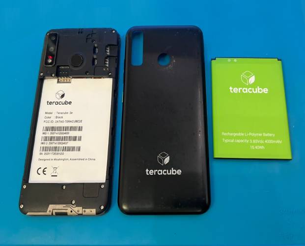
  1. Remove the battery cover and battery.
    New Project

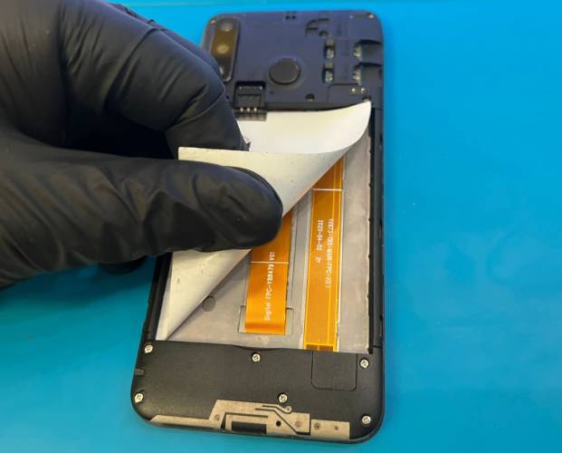
  2. Peel up the information sticker.
    New Project(1)

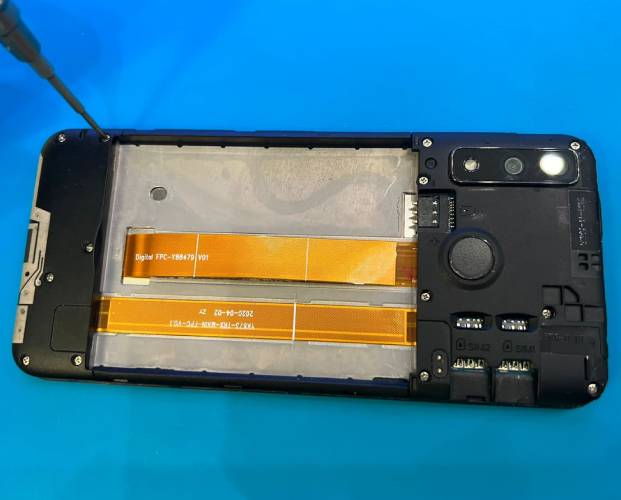
  3. Unscrew all the screws on the upper and lower board covers.
    UnscrewCovers

  4. Remove the upper and lower board covers.
    RemoveCovers

  5. Heat the display (optional for easier repair). A heat gun can be used, or a heated plate with controllable temperature, for example, the heated bed of a 3D printer.

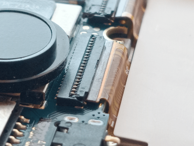
  6. Release the latches holding the ribbon cables in place on the motherboard and charging board. To release the latches, use a thin object to push upward on the connector where the cable enters it. It should flip up on a hinge, releasing the cable to be pulled out freely.
    2eRibbonConnector

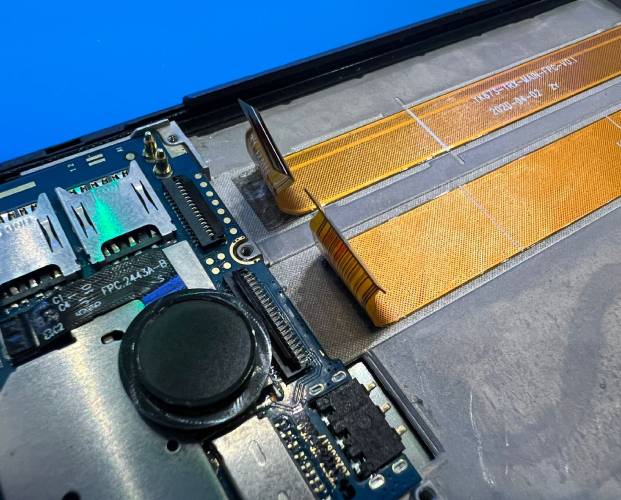
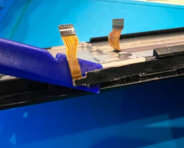
  7. Unseat the display ribbon cable and charging cable from the motherboard. Unseat the other end of the charging cable from the charging board.
    UnseatRibbonCables

  8. Disconnect the antenna cable from the charging board at the bottom.
    DisconnectAntenna

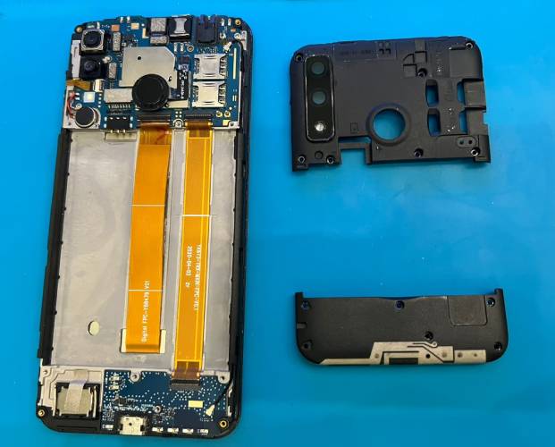
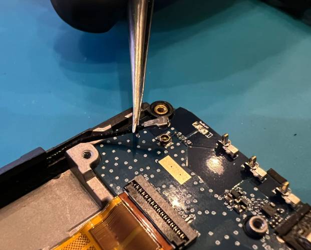
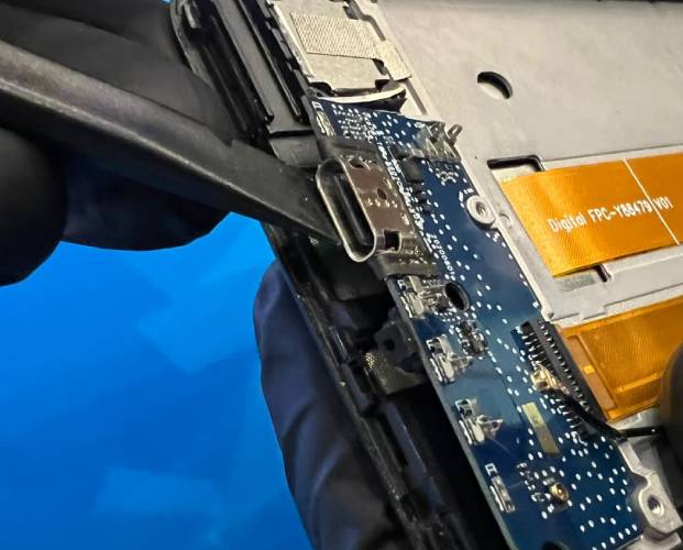
  9. Remove the logic board and charging port. The logic board is attached with adhesive and can be removed with gentle upward pressure at one edge. Mild heating may help to release the adhesive.
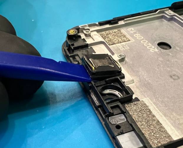
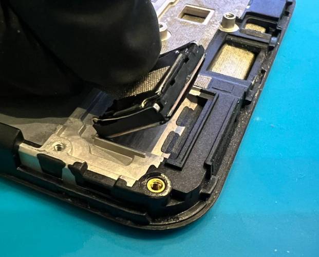
    RemoveChargingPort

  10. Remove the speaker.
    RemoveSpeaker

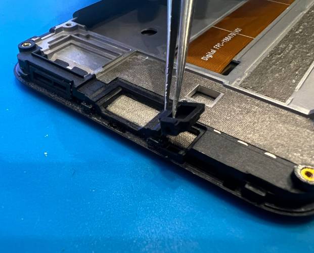
  11. Remove the microphone cover.
    RemovevMicCover

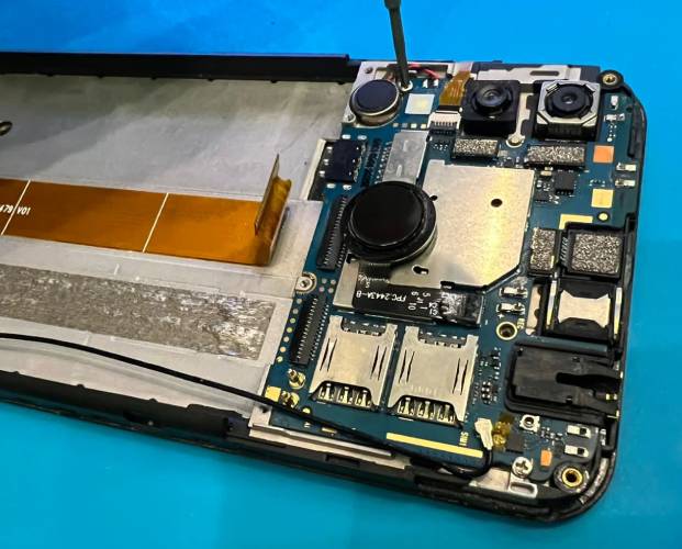
  12. Unscrew all of the motherboard mounting screws.
    UnscrewMobo

  13. Unseat the flex cable for the buttons.
    UnseatButtons

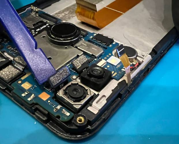
  14. Disconnect the flex cables for the cameras.
    UnseatCameraCables

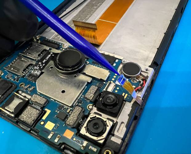
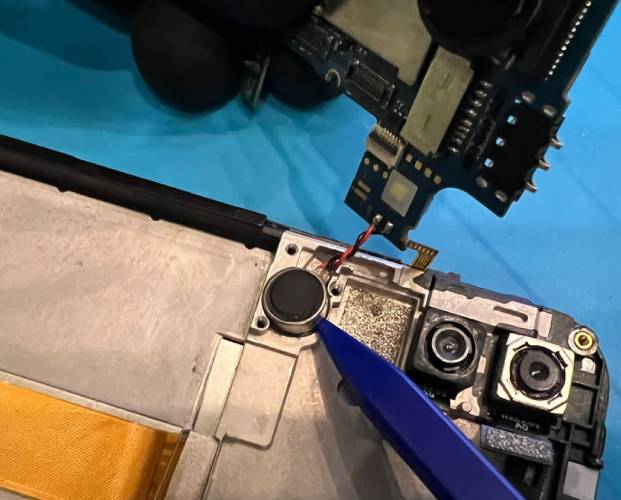
  15. Remove the vibration motor.
    RemoveVibrator

  16. Unplug the proximity sensor.
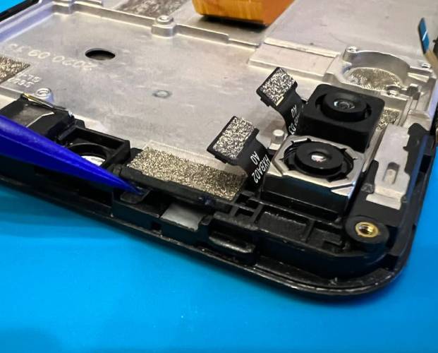
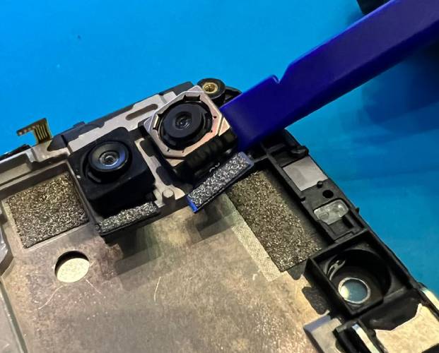
    UnplugProxSensor

  17. Remove the cameras.
    UnseatCameras

  18. Remove the front speaker.
    RemoveFrontSpeaker

  19. Remove the flex cable for the buttons from the frame.
    RemoveButtonRibbon

  20. Reassemble the phone in the reverse order on the new screen frame.

2 Likes

Thank you for posting this! Step 7 I think has an error - thatā€™s the charging board, isnā€™t it? Or maybe thereā€™s a different name, but I donā€™t think that is the motherboard

1 Like

Some more details for people who havenā€™t done this before. I will update this as I go, because right now Iā€™m a bit unsure of a few things

I would suggest a reordering of the steps. and a few notes along the way.
1
2
3
4 (just look for places to pry and be patientā€¦)
5. Be surgical. First focus on the small board on the bottom of the phone, which is what the next steps are focused on. Donā€™t over do it - try to work the parts a bit and youā€™ll feel them loosen as heat is applied. Iā€™ll mention everywhere below I think heat was useful.

BOTTOM OF PHONE

7- This is from the daughter board/charging board, not the motherboard. The smaller, simpler one at the bottom of the phone with the charging port.
NEW. Remove the ribbon cable from the charging board (I think - I did). To remove any of the ribbon cables, you have to lift the clip that clamps the cable down. Iā€™ll see if I can take a good image.
8- Remove the logic board. Itā€™s attached with adhesive, so this is where the heat gun/blow dryer is handy. Be careful, but rest assured that the bottom surface of the board is flat, so you can carefully wedge something under there (you donā€™t want to scratch it though)
10- That microphone cover sits overtop the mic component on the daughterboard and lives inside that little recess in the frame. Itā€™ll make sense when you see it.
17- Remove the front speaker CAREFULLY. Mine kind of came apart. You have to pry it. Thereā€™s a little metal frame, and then a sticker membrane that conceals a copper coil. Mine totally came apart, hopefully it works. Iā€™m curious how this thing works - there was no wire to it! Iā€™ll add an image later.
NEW (maybe)- Peel off the cable that attaches both boards. Use heat again (I used a blow dryer). It looks like they removed it in the images above, so maybe the replacement screen doesnā€™t come with this cable.

TOP OF PHONE (Motherboard side) - I havenā€™t done this yet. I am waiting for the replacement screen to arrive. I wanted to take the bottom bit apart to assess some damage to make sure it really was just the screen (I crushed my phone pretty violently under the lid of a carā€™s trunk :grimacing: ). Iā€™ll update this when I can!

I think these are how Iā€™d order the remaining steps, though.

6
11
12
13
18 (maybe here? Seems like a continuation of 13)
14
15
16
9 Normal ā€˜earā€™ speaker now. Probably be careful with this one too.

Images coming! (edited - the auto bulleted list clobbered my suggested order)

1 Like

Ooops.

Note to future readers. Pay close attention to this part of @robert 's post:

These instructions are applicable for the display screen part that comes with the mid-frame assembly (almost all screens shipped after May 2022). If you are not sure whether your part came with mid-frame or not, please contact us to confirm.
Here is a reference to the old article just in case you received the part without the mid-frame.

As of October 22, Teracube is still shipping the old screen type as well. So those instructions may be relevant.

Managed to get up and running and I guess I learned how to disassemble the whole phone too, for kicks :slight_smile:

You are correct - we have the old stock in Canada. Everywhere else it is the new type of screens.

1 Like

Just added youtube video link to the article

For anyone doing this repair themselves, note that the video has slightly different steps and in a slightly different order than the written instructions. Ignore the written instructions and watch the video instead, except for the latch release (step #6) as mentioned below.

Having just completed this process, I have to say, for a company whose main/only selling point is repairability, Iā€™m very disappointed with the quality of this guide - itā€™s a good overview but plenty of important details are missing. Iā€™m sure thereā€™s a much more complete SOP for your repair team/subcontractors: why not post an edited-down version of that instead?
And just for context, Iā€™ve been a professional EE for over a decade and am comfortable soldering 0402 and leadless parts, so the problems I describe below with my repair arenā€™t from a lack of fine motor skills or experience dealing with small, delicate objects.

Hereā€™s whatā€™s missing from the written instructions only (but shown in the video):

  • Removing the board covers: these have snaps in addition to the screws, so after removing the screws, youā€™ll have to feel gently around the edges of the covers and lift them at a few places to undo enough snaps that theyā€™ll come off. Unlike whatā€™s shown, it probably wonā€™t come off after poking at it in only a single location, as thereā€™s a few different snaps spread around the edges.
  • Removing the motherboard: youā€™ll have to disconnect the antenna cable connector at this end too (like in step #8 with the charging board).

Hereā€™s whatā€™s missing from the video (but covered in the written instructions):

  • Unplugging the flex (ā€œribbonā€) cables from the motherboard: the video shows these cables being pulled out by their corners, which seems dangerously likely to tear or kink the cables, and is done with the connector latches closed, in the ā€œlockedā€ position. The written instructions correctly note that the latches have to be released first (in step #6) - once the latches are released, pulling the cables out takes far less force. The best way to do this safely might be slipping something thin, like a straight section of some fine-tipped tweezers, underneath the ribbon cable just behind the connector, and using that to pull back on the entire cable at once instead of just by the corners as the video shows.

Hereā€™s whatā€™s missing from both of them, or mistakes that I made to avoid making yourself:

  • Removing charging board: Be warned that while the underside is mostly flat, the one component that is on the bottom, and can be easily damaged during this step, is the microphone - its location isnā€™t obvious from the top and the black cover blends in very well in the guideā€™s photos and video, so you likely wonā€™t know where it is until you know what youā€™re looking for. Do not try and lift the charging board from the point just to the right of the USB connector - this is where the microphone lives. I slid a very dull knife under the charging board to gently loosen the adhesive, while avoiding bending the board by lifting it from only one corner, but as I couldnā€™t tell the microphone was there (and itā€™s held on by understandably-tiny solder joints) managed to shear it off the bottom of the board without even noticing any extra force required. Good thing the replacement charging boards are only $30ā€¦
  • Antenna and motherboard-to-charging-board cables: Both these cables have to be removed from the frame (with the flex cable, by very carefully peeling it up) and re-installed on the new frame. Anyone going through the instructions will most likely figure this out themselves, but still should be explicitly documented. The antenna cable luckily has no adhesive, and can be simply inserted into its slot at the right side of the frame. Be careful of where you run the cable where it emerges from the slot and connects to both boards - if the board covers donā€™t go on all the way at first, this cable is probably sitting out of place and getting pinched between the cover and the frame somewhere.
  • Front-facing optics: Step #16 (and the equivalent in the video) is misleadingly labeled, as youā€™re not actually unplugging the proximity sensor, which is soldered to the motherboard - youā€™re just removing a little rubber gasket that sits between the motherboard and the frame. The part not shown in either set of instructions is that underneath this rubber gasket, thereā€™s two small pieces of plastic that also need to be transferred to the new frame/screen - a white-ish translucent sheet over the front-facing LED, and a clear plastic piece with a tube molded into it, that sits over the proximity sensor. I was able to get these out in the end with a fine-tipped pair of tweezers, but the clear piece likely will get scratched (luckily it doesnā€™t seem to keep it from working). Itā€™s difficult though because they sit flush inside the frame so trying to grab them by the edges doesnā€™t work very well, and they sit behind the glass on the screen, so you canā€™t push them out from the front either.
  • Removing speakers/vibration motor: The way that these parts sit, with adhesive at the bottom and walls enclosing them on all sides, makes these very difficult to remove intact. Heating the whole assembly from the bottom is useful not just to lift the charging board, but also to give yourself a better chance of getting your speakers and vibration motor out in one piece. This is a design problem - putting a few-mm-wide gap in one of the walls around each of these would go a long way towards being able to slip something underneath these parts and lift them from the bottom (the back-facing cameras are a good example of this being done right, since one side is open and so theyā€™re infinitely easier to remove). As it is, since the parts are too delicate to rely on lifting from the top, you have to stick your plastic ā€œspudgerā€ down the side of the tight-fitting hole that the speaker or motor sits in, and hope you can get it underneath the part without damaging it from the side either. mthomas above lost a speaker this way, and I lost the vibration motor - it turns out the gap in the vibration motorā€™s housing is at the bottom edge, so having to put a spudger blindly down the hole without being able to see what exactly youā€™re lifting, I ended up eviscerating the vibration motor (removing its case) instead of lifting it off of the frame. At least itā€™s easy to find cheap replacements for these (look for 8 mm diameter x 3 mm height vibration motors on eBay), but would have much rather not had to go to the trouble. I very much appreciate the rest of the 2eā€™s design being easy to repair by modern phone standards, but the lack of a channel to access the bottom faces of the speakers and vibration motor seems like the last major flaw to be fixed on that front, as screen replacement has to be one of the more common repairs, up there with swapping the battery and USB port.

Anyways, after putting it back together, now the front-facing camera and top speaker (for phone calls) arenā€™t working. Iā€™m hoping that the connectors just arenā€™t fully seated or that itā€™s a side effect of the missing microphone, but will have to see what happens once the new charging board comes and I replace that.

2 Likes

A couple more little bits of advice, after opening up my phone again to fix the remaining problems:

  • The orientation of the speakers matters: take notes or make a drawing before you remove the speakers from the old screen/frame. The back side of each speaker has two long metal springy levers (spring contacts) that stick up more on one side than the other: this is where they make their electrical connections through contact pads on the inside of the appropriate board cover. If the ā€œhigher sideā€ and ā€œlower sideā€ of the spring contacts are reversed, then it wonā€™t make an electrical connection and the speaker wonā€™t work.
  • The front-facing cameraā€™s connector was disconnected; this one seems to be harder for whatever reason to give a properly firm seating than the rear-facing cameras. Give it a gentle pull upwards with a fingernail to see if it moves.
2 Likes

Generally disappointed that the difficulty is pretty much on par with a traditional phone with the only exception being not needing a heat gun. I wish it could be as simple as opening the back, undoing a ribbon cable and some screws just like with any laptop. Hopefully in the future that will be a reality.

1 Like

Hello,

While replacing my screen as described in the video, the speaker split in two instead of coming loose and the internal winding is broken. Is it possible to get a spare speaker somehow?

Jan

1 Like

Hi, please reach out to support@myteracube.com and reference this thread. We do not have the speaker assembly as a separate part.

1 Like

QUESTIONs:

Replied on this thread

Hi,

My wife and I both have 2es which have both had replaced due to the screen adhesive failing and the screen coming away from the frame (great service on the replacements btw).

Now the same thing has been happening with one of the replacements. Whatā€™s the best way to address this before the screen becomes completely separated again? Is there a recommended adhesive to use? Is there a way of preventing this in the future?

Thanks

When I had this problem with my 2e (2020 model), I just stuck the screen back in place with 4 small drops of superglue along the edges. It seemed a lot easier and safer than the full screen replacement procedure, since the screen is fully functional.

My screen had fully separated, which made it easier to access the edges of the screen to apply very small drops of superglue. If the screen is in place, it may be tricky to do this without getting glue on the screen itself. This might cause problems.

Hope this helps.

1 Like